Effective Date: 15 June 98
The basic installed data will consist of curves of engine performance parameters in the bleed-off configuration. Data for these curves will be obtained from static engine calibrations and from the bleed- off portion of inflight testing.
The resultant curves will be used to define the basic installed gas generator characteristics. In addition, these curves will be used as input to the data expansion program as discussed later.
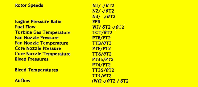
The basic installed engine data will be evaluated primarily in terms of engine pressure ratio (EPR) and Mach No. As an alternative, corrected fan speed, (Nl/(SQRT (Theta)t2) may be used in lieu of EPR. Listed below are the various normalized parameters which will be evaluated.
Thrust Setting Curves
Data for the construction of the generic high bypass thrust setting curves are furnished by engine manfacture. These curves are based on ratings for an uninstalled engine with estimated installation effects applied. The uninstalled ratings are derived such that the engine meets or exceeds specification thrust requirements. The final thrust setting curves will account for installation effects based on data obtained during the test program.
The thrust setting curves will include take-off, maximum continuous thrust (MCT) and maximum cruise thrust (MCRT) ratings. Typical thrust setting curves are shown in Figure 2b. Figures 1 through 72. It is anticipated that back-up thrust setting curves will be derived using fan speed (Nl) as the thrust setting parameter in lieu of EPR.
Data Expansion
The data expansion will be based upon generalized inputs derived from curves from flight test data as described in Section xxx5.0. These data include engine inlet and exit pressures and temperatures, bleed flow pressures and temperatures, fuel flow and rotor speeds. The format for the flight test data will be chosen on the basis of minimum effect of flight speed, altitude and ambient temperature conditions.
It is expected that the calculation method for expanded data thrust will be identical to that used for flight test data reduction. Basic flight test data correlations will be developed with no bleed flow conditions; then these are corrected by supplementary flight test data to the specific bleed condition.
Several bleed configurations will be developed for data expansion; these include normal bleed operation as well as wing anti-icing, engine anti-icing and conditions with one or two engines inoperative.
All appropriate limitations (physical as well as engine ratings), will be used in the expansion process.
The procedure for data expansion consists basically of
(1) defining conditions (Mach, altitude, engine power, etc.);
(2) obtaining necessary parameters (temperatures pressures, etc.) from curves based on Flight Test results;
(3) calculating thrust and the required expansion parameters, correcting for bleed and the appropriate limitations where necessary.
This is shown schematically in the flow chart on Figure 2b. .
Short Form Thrust
A short form of thrust look-up chart will be developed which will require the definition of only three quantities to determine thrust (Mach No., Altitude, and (EPR). The charts to be developed are discussed below.
Basic Thrust Chart
A thrust chart as shown below will be developed for the normal bleed configuration.
This basic thrust curve may require an altitude correction, and possibly an incremental correction for the center engine to account for PT2 probe recovery. The data to generate this curve will be developed from the data expansion program.
Flight Idle Map
A flight idle map will be developed from test data in one or both of the following forms:
Thrust During Take-Off
Thrust will be calculated continuously during take-off to determine the thrust lapse rate. An accurate ground speed will be determined using an airfield space positioning system in conjunction with weather station data. The following curve will be developed to confirm the theoretical thrust lapse rate:
Reverse Thrust
Reverse thrust data will be obtained at various power settings during landing in order to develop a reverse thrust curve as shown below. The airfield space positioning system and weather station data will be used to determine an accurate ground speed and temperature. The calculation procedure for reverse thrust is discussed later.
INLET ANALYSIS
Engine inlet performance characteristics, including inlet recovery and distortion, will be evaluated on one wing pod engine and on the center engine installation.
Instrumentation
Each inlet instrumentation installation consists of an inlet rake employing ten equally spaced spokes, each having eight total pressure probes. The probes are located radially such that they are equally split between the bypass and gas generator flows with approximately equal area weighting within each stream. Inlet total temperature is measured from temperature probes on every other rake spoke.
Recovery
Inlet total pressure recovery is the average total pressure level (#1#2) at the engine inlet face relative to the freestream total pressure (PTO).
The inlet total pressure can be computed as the sum of the area weighted average pressure at the bypass inlet and the gas generator inlet. This allows separate analysis of the bypass and gas generator recovery.
The bypass inlet recovery is
# (PT2BX FBX)/(PTO) #B = (PT2B/PTO) = FBB (8.1)
where,
#B = Bypass inlet recovery
PT2B = Average area weighted bypass inlet pressure
PTO = Freestream total pressure = (PAM + qC)
PT2BX = Measured bypass total pressure at rake probe location X
FBX = Area weighing factor for rake probe location X
FBB = Bypass area weighing factor
A similar equation is used to determine the gas generator inlet recovery (###G).
The overall average inlet pressure is computed by
(###FB- + ##;#FBC#)
# = PT2/PTO = # FBB + # FBGG (xxxx8-2)
The inlet recovery will be evaluated from data acquired under steady state conditions and presented as a function of airflow and Mach No. as shown below.
The inlet airflow (Wo###f2/##T2), is obtained from an airflow map derived from test data.
An additional analysis of inlet recovery consists of evaluating each total pressure probe reading in terms of its angular and radial location for a given condition, as shown below,
The above plot provides analysis of total pressure readings in terms of the probe locations, (ideally, the total pressure readings should be symmetrical with respect to angular rake location). In addition, the recovery at the inlet pressure probe (PT2P) for EPR will be evaluated for both wing pod and center engine installation. It wi11 be presented as a function of airflow and Mach No. similar to the previously described presentation for inlet recovery.