
Effective Date: 15 June 98
The thrust method used for the airplane/high bypass performance evaluation employs nozzle internal rake temperatures and pressures to calculate gross thrust and nozzle airflow. In general, this method uses nozzle total pressure divided by ambient pressure (PT/PAM) to evaluate both the airflow and the gross thrust produced by the engine. The classical method of calculating net thrust on low bypass engines is to determine gross thrust from nozzle measurements and ram drag (airflow) from fan speed. Since the method selected for the airplane/high bypass uses the nozzle airflow to determine nozzle gross thrust, the accuracy of net thrust (gross thrust minus ram drag) is greatly increased.
Airflow
The cooling airflow for the nacelle ventilation, IDG oil cooler, and the air cooled oil cooler (ACOC), is extracted from fan (bypass) air and must be accounted for in the evaluation of total airflow.
The Zone 2 and 3 ventilation air flows are computed as follows:
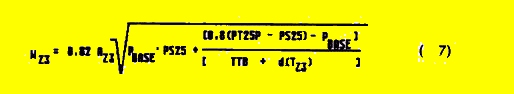
When the ventilation analysis has been completed (Section 9.0), Zone 2 and Zone 3 flow rates will then be calculated from these curves, derived from flight test data.
The IDG oil cooler airflow (WIDG), the ACOC airflow (WACOC), and an additional term WL which accounts for fan airflow leakage are based on results of Engine manfacture testing. The calculated fan bleed therefore is the sum of the above bleed flows,

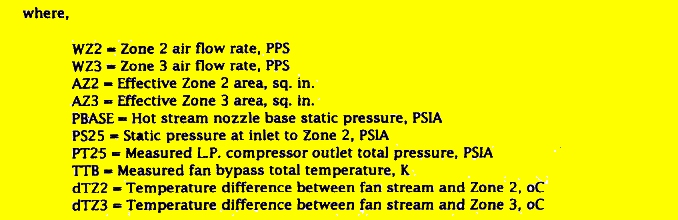
The ideal bypass airflow is computed as follows:
(Note that for a rigorous analysis the specific heat ratio should be a function of the static temperature; however, the error introduced by using the total temperature is considered to be insignificant.)
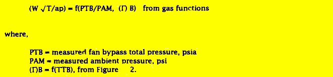
The bypass nozzle airflow is:
The fan exit airflow (W25) is the bypass nozzle airflow plus the fan bleed. Stated mathematically:

The core engine exit gas flow (WE) is calculated in the same manner as the bypass airflow calculation using PT8/PAM, WE' CDE' CDRE' and AE.
The core engine inlet airflow is equal to the exit flow plus the compressor bleed flow, less the addition of fuel flow. In equation form, this is expressed as

The fan compressor or total airflow inlet is equal to the core engine inlet flow plus the fan exit airflow,

The total inlet airflow is used in conjunction with the inlet
analysis , as well as the ram drag portion of
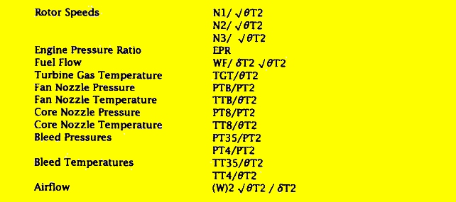
the thrust calculations. The normalized total inlet airflow  will be evaluated in one or more of the following
forms:
will be evaluated in one or more of the following
forms:
In the above evaluations, corrections due to altitude or Reynolds Number Index may be required.
Gross Thrust
The calculation of fan and core gross thrust consists of determining the gross thrust parameter, calculating the ideal gross thrust, and applying the coefficient to obtain the actual gross thrust. The fan gross thrust parameter is a function of the fan nozzle expansion ratio and the specific heat. The derivation is discussed later,

The ideal fan gross thrust is,

Next, the fan velocity coefficient (CVB), is used to calculate the actual fan gross thrust as follows

The core engine gross thrust (FLzE) is calculated in the same manner as the fan thrust using PT8/PAM. CVE' and AE.
The total gross thrust is the sum of the fan and core gross thrust,

Drag
The ram drag, or inlet momentum, is calculated as follows:
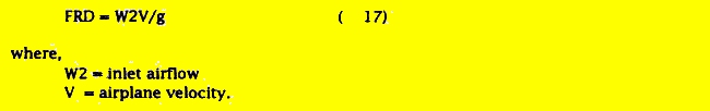
The above form of the inlet momentum equation is simplified into the following form:

Two additional drag terms have been defined, jet effects and spillage drag. These two drag terms are not accounted for in the calculation of net thrust because the reduction and expansion process will use the same calculation procedure and these drag terms cancel out.
The spillage drag increment (FSD) accounts for inlet spillage at low mass flow ratios. The spillage drag is a function of Mach number and mass flow ratio. The spillage drag is determined from data from wind tunnel tests of a full span model with flow- through nacelles. Typical spillage drag is shown in Figure 3.
The remaining drag term is termed jet effects. This thrust increment accounts for the interaction of the pylon or aft fuselage and the engine flow field. The effect of the airplane flow field on engine thrust has been measured in the wind tunnel on a model. Typical jet effects (FJET) are shown in Figure 4. for the center engine installation. It should be noted that jet effects are additive, since jet effects reduce form drag.
Net Thrust
At this point in the calculations, all the terms required to compute the net thrust have been defined. Propulsion net thrust may be computed as the gross thrust less the ram air drag as follows

The net thrust calculated in Equation 19 will be used to (1) establish the relationship between net thrust and (cockpit) engine pressure ratio (EPR), and (2) evaluate the performance of the airplane by using this thrust value in conjunction with aerodynamic analysis (Reference 2).
Windmilling Drag
The estimated windmilling drag for a pod and center engine installation is shown in Figure 5. This drag will be used in determining engine-out performance analysis. This data has been derived from information supplied by engine manfacture, plus the results of model tests.
Theoretically, the methods previously discussed to calculate net propulsive thrust should reproduce windmilling thrust (drag) for an inoperative engine. An attempt will be made to calculate windmilling drag by these methods, however, the instrumentation limitations at low pressure and temperatures may negate this procedure.
Reverse Thrust
In the reverse thrust mode the hot stream spoilers deploy and the core engine exit flow is diverted 90 degrees so as to produce no thrust in the longitudinal direction. Therefore, FgE = 0 in the reverse mode.
The fan airflow and gross thrust are calculated the same way as in the forward mode, except that the flow and velocity coefficient are modified to account for the flow exiting through the reverser cascades. In addition. the fan airflow (WB) is now calculated as a function of PT25P and TT25 instead of PTB and TTB, since the latter two measurements are located aft of the reverser blocker doors. PT25P is a measured value and TT25 is determined from the curve shown in Figure 6. The net thrust in reverse is then calculated as follows:
The axial component of the fan reverse thrust is,
For the present, the reverser effectiveness is assumed to be a constant value (.513), however, test results may indicate that effectiveness is a function of fan pressure ratio or fan rotor speed.
The base drag (FDR) in reverse, acting on the deployed spoiler and reverser doors, is obtained from Figure 7.
The net thrust in reverse is,