
The bleed flow rate is,

The specific heat ratio from Figure 3.
Effective Date: 15 June 98
Compressor bleed air is obtained from the intermediate (IP) and high pressure (HP) compressor, and routed to the appropriate bleed supply ducts. For most of the flight regime (take-off, climb, and cruise conditions) the supply source is IP air. For other conditions, idle descent, it is necessary to use HP air either solely or partially in which case the IP air is boosted by feeding the HP air through the nozzle of a mixing ejector. HP air is also used to boost the temperature of the IP air to a minimum of 450 Deg F for example whenever wing anti-icing is required.
Bleed Flow Calculation
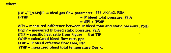
From ideal gas flow, the IP bleed flow rate for each engine is calculated as follows:
The bleed flow rate is,
The specific heat ratio from Figure 3.
The HP bleed flow (WHP) is calculated in the same manner using HP bleed measurements.
Bleed Data Evaluation
Analysis of the compressor bleed data, from the propulsion analysis standpoint, consists primarily of
(1) determining bleed effects on engine performance parameters,
(2) generalizing bleed parameters for use in the expansion program, and
(3) normalizing bleed flow, as a function of EPR and altitude for example, for a given bleed configuration.
To determine the effects of bleed on engine performance comparison of various engine parameters with and without bleed will be accomplished. The bleed effects will be normalized with respect to percentage bleed flow and analyzed as a plot of the following form, for example,
where:
# WF = change in normalized fuel flow per % WBLD percent bleed constant EPR lb/%.
The percent bleed is the ratio of the calculated bleed flow to the calculated core engine airflow.
Bleed flow rates will be evaluated by normalizing measured bleed flows as a function of the EPR and altitude for a given configuration. An example of this type plot is shown below. It is possible, however, correction factors for other variables (such as Mach No.) may be required.